
FD SOLUCIONESOPTICAL CONNECTIONSDiscuss Your Link
Home / Interconnection Plans
Interconnection plans

A Clear Route from Port to Port

Plan the interconnection as a complete channel: equipment interface, patch lead, distribution point and physical route. The layouts below are planning scenarios, not completed customer projects.

Three planning situations

Choose the Connection You Need to Organise

Use the existing installation record as a starting point. Confirm the required interfaces and access constraints before deciding what can be retained or changed.

Equipment room racks for a structured optical interconnection plan
01 / Between racks

Rack Interconnection

Define the channels between active equipment and the distribution field. Group the port schedule by rack, interface and service requirement before choosing patching density.

  • Map endpoint ports and the intermediate panel positions.
  • Check fibre category, connector polish and equipment reach.
  • Reserve service access and document spare capacity.
Review panel options →
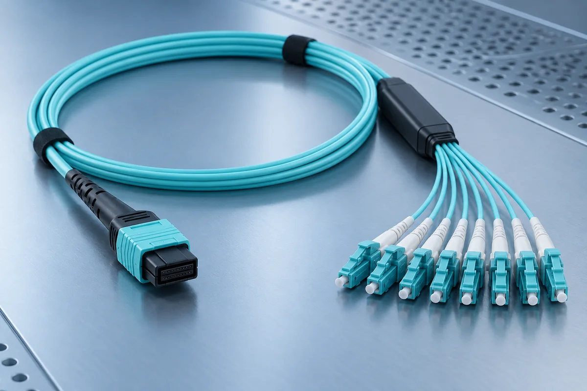
MPO assembly for a planned high density optical equipment change
02 / During change

Equipment Moves & Interface Changes

A new equipment interface can affect the existing channel even when the installed cable remains in place. Record what changes at each end before selecting an assembly.

  • Verify the current connector and multifibre polarity plan.
  • Separate retained links from replacement assemblies.
  • Agree service interruption, temporary patching and retesting.
Check polarity requirements →
Protected overhead fibre pathway connecting equipment locations
03 / Along the route

Managed Fibre Pathways

Bring rack entries, pathway branches and cable handling into the same route drawing. Installation convenience should not compromise bend control or future access.

  • Locate entries, transitions and shared route sections.
  • Check product-specific bend, loading and support limits.
  • Plan labels, change access and the handover record.
Explore routing products →
One channel, several interfaces

Follow the Connection Before Finalising the Parts

This simplified chain is a planning aid. The actual channel can include different equipment, panels, splices and passive components.

01

Equipment Port

Host interface, wavelength and optical operating limits.

02

Patching

Connector pair, fibre category, polarity and lead length.

03

Distribution

Panel arrangement, termination and accessible routing.

04

Remote Endpoint

Compatible interface and complete channel acceptance.

Prepare before procurement

Four Records That Make the Enquiry More Useful

Even a preliminary schedule helps identify what is known and what still needs a site check.

Endpoint map

What Connects to What?

List source and destination racks, equipment and ports. Mark planned links and existing links separately.

Route sketch

Where Will Fibre Run?

Show the intended pathway, panel positions, entry points and measured or estimated distances.

Interface schedule

Which Optical Details Are Fixed?

Record fibre type, connector and polish, host interface, polarity and any agreed passive devices.

Acceptance scope

How Will the Link Be Accepted?

Agree identification, continuity, polarity, loss testing and the records to retain at handover.

Bring the layout and port list

Turn the Connection Plan into a Defined Product Scope

Share the known interfaces, constraints and proposed installation arrangement with FD SOLUCIONES.

Discuss Your Interconnection